90 degrees bend angle.
Calculating layout sheet metal corner radius bend.
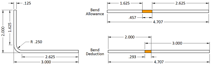
It has a material thickness of 0 250 in.
Bends that are in the same plane need to be designed in the same direction to avoid part re orientation to save both money and time.
Use this document to choose values that are both manufacturable and meet your needs.
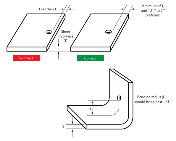
The most important considerations when bending metal is the min.
Bend allowance is the amount of metal to be added to the total layout.
Bend relief is provided at the end of bending edge in sheet metal design to avoid any crack tearing in the corner.
The legs are each 1 000 in and the dimension to the apex between the part edge and bend apex is 3 836 in.
And an inside bend radius of 0 250 in.
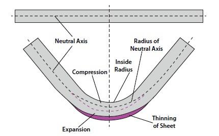
Figure 2 illustrates the sheet that is bent with the bend angle of 90 degrees.
Relief height is generally kept greater than two times of sheet thickness plus bend radius.
Cells on the right will output the desired values.
When the sheet metal is put through the process of bending the metal around the bend is deformed and stretched.
With this free online tool we quickly get the sheet metal bend deduction and therefore the sheet metal blank initial flat length from the finished part measurements.
Note that in the formulas below ir represents the inside bend radius and mt represents the material thickness.
It is most economical to use a single bend radius throughout the design but if necessary you can utilize multiple radii.
Bend radii minimum bend sizes.
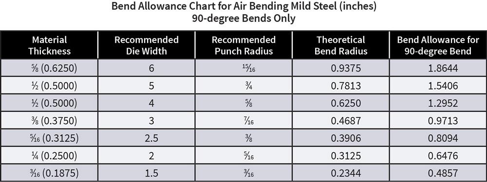
For all methods we calculate the bend.
Keeping the bend radius consistent will also make parts more cost effective.
Understanding the bend allowance and consequently the bend deduction of a part is a crucial first step to understanding how sheet metal parts are fabricated.
The bend allowance and bend deduction are two measures that relate the bent length of a piece of sheet metal to the flat length.
After bending the sheet we need to do some measurements as shown in figure 2.
When bends are made smaller than the required min.
Therefore the bend allowance added to the flange lengths is equal to the total flat.
From there we can calculate the k factor and the bend deduction.
You only have to insert interior angle flange lengths k factor inside radius and material thickness.
Sheet metal bend brakes are used to bend material into the parts desired geometry.
As this happens you gain a small amount of total length in your part.